Home>>CVT Working principle >> Working principle
The principle of CVT
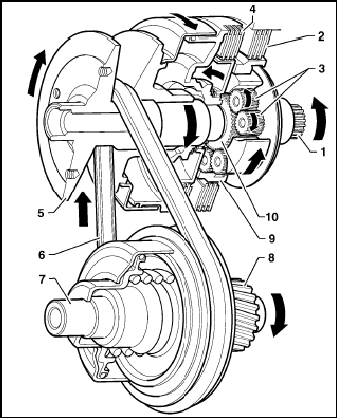
Transmission cross section
.png)
1. Torsional damper / Flywheel
2. Fluid pump
3. Reverse clutch
4. Planetary gearing
5. Forward clutch
6. Steel belt
7. Primary pulley
8. Secondary pulley
9. Intermediate shaft
10. Differential
Basic Principles of Continuously Variable Transmission
The VT2-VT3 consists of a number of elements that can be divided into three groups, depending upon their function.
Group One – Mechanical Torque Flow
Elements providing the mechanical torque flow through the transmission.
Group Two – Control system
These elements relate to the control system. This system enables the transmission to transmit power and to vary the ratio in a proper way, according to load conditions and driver demand.
Group Three – External Connections
Some elements have external connections with the transmission. Some of these elements are either inside the gearbox, or immediately connected to it. Others can be part of the system, but can be located elsewhere on the vehicle.
Group One – Mechanical Torque Flow
Planetary gear set
The planetary gear set enables the transmission to provide a drive torque in two directions, forward and reverse. Engine torque always enters the transmission through the input shaft of the planet carrier. This carrier can be directly connected to the sun-wheel by closing the forward multi-plate clutches. When it does, the epicyclic gear set rotates as one unit, and engine torque is transmitted directly to the primary pulley. The planet gears do not transmit any torque, therefore no mechanical loss will occur in the planetary gear set and the primary pulley will rotate in the same direction as the engine. This is the forward drive mode.
In reverse mode, the annulus of the planetary gear set is held stationary by closing the reverse multi-plate clutches. Three pairs of planet gears are driven
.png)
by the planet carrier, forcing the sun-wheel to rotate in the opposite direction.
There is a small multiplication of torque being transmitted since the ratio of the epicyclic gear set is 1:1.1, in order to compensate for frictional losses within the planetary gear set itself.
1. Planet gears
2. Input shaft
3. Sun gear
4. Annular gear
Fig. : Planet gears
Multiplate clutches
There are two Multiplate wet clutch packs; one forward and one reverse. Each pack has three friction plates providing six friction surfaces. The hydraulic pressure controls the clutches to allow the vehicle to move away smoothly by every throttle opening. By controlling the clutch slip it also allows the vehicle to be held stationary after the drive gear is engaged. Oil from the oil cooler is directed to the clutch plates to prevent overheating of the friction surfaces.
.png)
1. Forward clutch pack
2. Reverse clutch pack
Fig. : Planetary gear set showing clutch plates
Pulleys and steel belt
The main design feature of the CVT is a pair of steel "V " shaped pulleys connected by a steel drive belt. The distance between centres of the primary and secondary pulley is 155 mm. Each pulley consists of one fixed half and one axially slideable half, both having 11 degree sloping sides. The proven 24 mm wide "Van Doorne" push type drive belt is used to transfer torque between the pulleys (applications for higher torque values can make use of a 30 mm drive belt). The belt is lubricated and cooled by an oil jet from a nozzle. Both moving halves are situated diagonally opposite to each other in order to reduce misalignment of the drive belt during shifting. Each moving half is connected to a hydraulic cylinder/piston. Hydraulic pressure is controlled by the control system, described in the section titled ‘Hydraulic system’. Ball splines prevent the moving halves from rotating relatively to their fixed partners.
Torque transmitted by the planetary gear set acts directly onto the primary pulley, as the sunwheel is splined to it. The steel drive belt transmits the power from the primary pulley to the secondary pulley and the power from the secondary pulley is then transmitted to the pinion shaft.
Torque and speed of the secondary pulley are determined by the position of the drive belt.
The sizes of the two pulleys are designed to provide a range of ratios from 2.416:1 to 0.443:1 resulting in a ratio spread of 5.45. The high overdrive ratio is particularly advantageous in respect to fuel consumption.
The steel drive belt has approximately 450 segments and is held together by 24 steel bands, 12 on each side.
.png)
1. Steel bands
2. Steel segments
Fig. : Drive belt
Intermediate shaft
The intermediate shaft (or pinion shaft) creates a two-set helical gear reduction between the secondary pulley and the differential. In this way, the rotational direction of the drive shafts will be correct. The reduction between the secondary pulley and the drive shafts can be made large enough to give good vehicle performance. The intermediate shaft is supported by two conical bearings, one in the clutch housing and one in a separate bearing support.
.png)
1. Primary shaft drive gear
2. Differential crown wheel
3. Pinion drive gear
4. Transfer gear pinion shaft
5. Secondary shaft drive gear
Fig.: Crown wheel & pinion
Differential
Drive torque on the crown wheel is transmitted to the vehicle wheels through a differential, just as in a manual transmission. The crown wheel is bolted to the differential case with 8 bolts. The drive shafts are fitted to the differential with conventional CV joints and seals. Conical bearings are used to support the differential.
.png)
1. Differential bearing
2. Differential casing
3. Differential cross shaft
4. Differential planet gears
5. Differential crown wheel
Fig. : Differential assembly
Ratio changes
Unlike conventional planetary automatic transmissions that provide a limited number of gear ratios, usually four, five or six, the CVT, as its name suggests, continuously varies the gear ratio. A low gear (low ratio) makes it easier to pull away from a rest position, the drive pulley diameter being relatively small, while the driven pulley diameter is large by comparison. The drive belt is used to transmit power and torque. As acceleration takes place it becomes possible to select a higher ratio by increasing the diameter of the drive pulley while, at the same time, decreasing the diameter of the driven pulley. This degree of change can be controlled to ensure that the most suitable ratio is provided.
The CVT uses a primary pulley and a secondary pulley. Both pulleys have one fixed half and one mobile half, controlled by hydraulic pressure. The position of the drive belt on the pulleys will determine the ratio. If the mobile half of the pulley is close to its opposite half then the drive belt is forced to travel around the outer circumference. When the pulley is open wide then this circumference is reduced. The primary and secondary pulley mobile halves are diagonally opposed so when the drive belt diameter is reduced on the primary pulley, it increases on the secondary pulley.
To pull away, a low ratio is required. To provide this, the primary pulley is open, allowing the drive belt to sit down into the pulley and forcing it to run around the outer of the closed secondary pulley. As vehicle speed increases, a higher gear ratio is required. To do this, the primary pulley gradually moves towards its fixed partner, increasing the pulley circumference. At the same time the secondary pulley is forced apart reducing pulley diameter, therefore creating a higher gear ratio. An overdrive ratio is obtained when the primary pulley is fully closed and the secondary pulley is fully open. The secondary pulley is now forced to rotate approximately two and a half times for every turn of the primary pulley.
.jpg)
Input from the engine
2 Output to the wheels
3 Drive pulley at minimum
diameter (Low)
4 Driven pulley at maximum
diameter (Low)
Fig.: Pulleys in low position
.png)
1 Input from the engine
2 Output to the wheels
3 Drive pulley at maximum
diameter (overdrive)
4 Driven pulley at minimum
diameter (overdrive)
Fig.: Pulley positions in high ratio (overdrive)
Selector lever in the Neutral or Park position
In this condition motion is not transferred to the wheels as both clutches for reverse (2) and forward gears (4) are disengaged.
- The transmission input shaft (1) turns at the same speed as the engine.
- The reverse gear clutch (2) is disengaged.
- The forward gear clutch (4) is disengaged.
- The planetary gears (3) idle around the sun gear.
- As the sun gear does not move, neither does the primary pulley (5), the secondary pulley (7) and, subsequently, the vehicle.
.png)
1. Input shaft
2. Reverse gear clutches
3. Planetary gears
4. Forward gear clutches
5. Primary pulley
6. Steel drive belt
7. Secondary pulley
Fig. : Pulleys & gear train
The engine can only be started in Neutral or Park, as with any automatic transmission. In the Park position, there is a mechanical lock that prevents the vehicle from moving forward or backward. The Park position should only be engaged at standstill to avoid transmission damage.
Selector lever in drive position
Under this condition, the forward motion is transferred to the wheels as the forward clutch (4) is engaged.
- The transmission input shaft (1) turns at the same speed as the engine.
- The reverse clutch (2) is disengaged.
- The forward clutch (4) is engaged.
- The planetary gears (3), the sun gear and the annular ring gear of the epicyclic train rotate together.
- The primary pulley (5) turns at the same speed as the engine in the forward gear direction.
- The secondary pulley (7) turns in the forward gear direction at a speed that depends upon the belt ratio for that operating condition.
.png)
1. Input shaft
2. Reverse gear clutches
3. Planetary gears
4. Forward gear clutches
5. Primary pulley
6. Steel drive belt
7. Secondary pulley
8. Secondary pulley
9. Input shaft
Fig. : Pulleys & gear train
Selector lever in the Reverse position
Under this condition, the reverse clutch (2) is engaged and makes the annular ring gear (9) lock to the transmission case. The planetary gears (3) force the sun gear (10), the primary pulley (5) and the secondary pulley (7) to turn in the opposite direction to the transmission input shaft (1).
Therefore reverse gear is now selected.
- The transmission input shaft (1) turns at the same speed as the engine.
- The reverse clutch (2) is engaged.
- The forward clutch (4) is disengaged.
- The annular gear (9) is linked with the transmission case by means of the reverse clutch (2).
- The planetary gears (3), which are driven directly by the transmission input shaft (1), turn around the annular gear (9). Therefore they force the sun gear (10), the pulley (5) and the secondary pulley (7) to turn in the reverse gear direction.
1. Input shaft
2. Reverse gear clutches
3. Planetary gears
4. Forward gear clutches
5. Primary Pulley
6. Steel drive belt
7. Secondary pulley
8. Secondary pulley
9. Annular gear
10. Sun gear
Fig. : Pulleys & gear train
Group Two – Control System
The functions of the control system are:
1. To match the clamping force on the steel drive belt tension with engine torque, preventing belt slip.
2. To control the operation of the forward and reverse clutches during driving and take off.
3. To provide the optimum transmission ratio for all driving conditions.
4. Provide the necessary lubrication and cooling oil in the gearbox.
Oil pump
The pump within the transmission is an external gear pump. The engine drives it via a shaft through the hollow primary pulley shaft. The pump shaft is splined to the planet carrier, which always run at engine speed. The discharged volume is about 10 cm³ per revolution. System pressure can reach 40 to 50 bar depending on input torque.
.png)
1. Oil pump drive shaft
2. Oil pump assembly
Fig : Oil pump complete
The oil pressure is used both for controlling the transmission hydraulically, and for lubrication purposes.
.png)
1. Oil pump inlet
2. Oil pump oil seals
Fig: Oil pump inlet
Variator control
The variator control ensures the minimum clamping forces necessary to avoid slippage between belt and variator and in parallel it provides the ratio value (calculated from the in- (or primary) and output (secondary) speeds of the variator) in accordance to the target ratio value given by the driving strategy. The deterioration over lifetime of the control behaviour is kept in a range that there is no noticeable deviation on comfort and / or clamping force capability.
Clamping force control
The clamping force management ensures that the pressure levels necessary to provide the demanded forces at the variator (to prevent belt slip) have minimized impact on the efficiency of the transmission, in order to minimize fuel consumption.
Besides "normal driving" the clamping force management also takes into account special driving situations with torque peaks from input and/or output side of the transmission in order to provide the maximum protection for the gearbox. The control takes into account the influence of ABS braking, blocking wheels (when driving without ABS) and other drive line control systems (like ESP, anti-skid control). It also recognizes and takes into account special road surfaces and conditions like driving through holes and over curbs, transitions between low and high friction, slipping wheels (e.g. on low friction road surfaces)
The software also compares the transmissions dynamic torque transmitting capabilities (while taking into account the systematic delay times of the hydraulic system) with the predicted input torque for the transmission. If the clamping force management will detect situations, where the demanded clamping forces cannot be sufficiently covered a request for torque reduction will be sent to the ECU to bring the engine torque into an appropriate range. This functionality is included to protect the transmission.
When there is no electronic drive by wire system available in the vehicle platform, the torque signal comes from the ECU through CAN. If CAN drops out, a predictive torque signal will be generated by the TCU software itself.
Ratio control
The variator ratio is controlled via the balance between the forces induced on the primary and secondary pulley by the primary and secondary pressure. Via the primary and secondary speed sensor signals, the ratio can be calculated and the outputs (the pressures) can be adapted to meet the ratio set point. The minimal pressure levels are determined by the clamping force strategy. A physical model of the variator helps to adjust the pressure levels quickly to variable operating points. The control software also takes into account disturbances from other elements in the transmission and is developed with the aim to minimize delays at tip-in and tip-out and minimal overshoots to target ratio (in order to improve fuel economy).
In order to ensure that the mechanical and durability limitations of the transmission are met, several limitations on the driving strategy are set. Besides speed limitations there are also software functions implemented to keep the ratio gradient (setpoints) within the allowed ranges. Furthermore, the software avoids engine speeds above certain thresholds depending on vehicle speed and status of the position Lever (POS). In order to achieve this restriction, the software sends a request for torque reduction to the engine or provides an up shift if the car is not at standstill.
Transmission control unit
The software that controls the transmission is integrated in the TCU (Transmission Control Unit). The TCU is installed in the passenger compartment.
Group Three – External connections
Oil cooler connections
There are two oil cooler pipe connections on the front of the transmission casing. An oil cooler is fitted alongside the radiator of the engine to maintain the transmission oil temperature below 120°C.
The oil flows out of the transmission out of the right side connector. This transmission oil output (Oil TR OUT) should be connected to the Input of the oil cooler which is the lower connector on the oil cooler.
The oil flows out of the oil cooler through the top connector of the oil cooler. This top connector should be connected to the transmission left side connector (Oil TR IN).
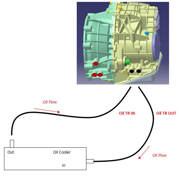
Fig: Oil cooler pipe connections
Selector shaft
Possible shift positions for the VT2-VT3 transmission are Park, Reverse, Neutral, Drive and Sport position.
The configuration of the selector lever is customer specific. For safety reasons it is recommended to implement a shift lock in the mechanism, to provide an idiot start protection.
It is also possible to have a tip-function included. This means that additional interfaces to the TCU are to be provided in order to get the tip-signals to the TCU. Also the calibrations for the maximum engine speeds can be adapted within certain limits.
Main connector
The connector consists of 16 pins and is located in the transmission casing. The harness connection is via a circular connector.
.png)
Fig: Harness block on gearbox
Torsional damper
The engine is connected to the input shaft in the transmission, via a torsional damper, instead of the torque converter used by more conventional automatic transmissions.
This torsional damper is not a part of the transmission. Punch strongly recommends the use of a so-called Dual Mass Flywheel.
|